How to DIY a CNC Machine from Scratch for Beginners
How to Build a CNC Machine from Scratch? - DIY Guide
Learning how to build a CNC machine from scratch is easier than you might think. We have broken down the DIY process into a series of easy-to-follow steps for beginners. From buying parts to installing software, our DIY guide will walk you through how to easily make your own CNC machine.
What is a CNC Machine?
A CNC machine is an automated power tool that uses computer program to control the motor to drive the three axes of X, Y and Z to move back and forth along the tool path generated by CAD/CAM software according to G-code commands. Finally, the tool on the spindle completes the carving, cutting, and milling results.
Things To Consider
When it comes to CNC machines, everyone will think of its high cost and complex programming operations, which make us feel unfathomable about it. In fact, we know and learn CNC by making some simple and low cost CNC machines, which has enabled us to upgrade from a beginner to an expert in modern CNC technology. The difficulty of DIY a CNC machine lies in the high cost of the machine kits and the difficulty of machining, and the setting and use of the software is relatively simple. After a month of studying and researching CNC, I decided to build my own Mach3 controlled CNC machine kits using locally available materials. Building Difficulty: Moderate. Building Duration: 16 Days. DIY Tools: Bench vices, electric drills, hand saws, sample punches, taps, reamers, calipers, benders, and screws.
Getting Started
This guide is all about creating a functional CNC machine with the following features. 1. The gantry structure has good stability, large processing format, compact and lightweight desktop design, light weight and easy to carry. 2. It can be used to cut and mill PCB, PVC, acrylic, MDF, wood, aluminum, and copper. 3. Its machining accuracy can reach 0.1 mm, which can meet the requirements of most PCB boards, molds, stamps and signs. 4. Its cost is under $1,000, and the assemble is convenient and easy. 5. The parts and raw materials used can be found or bought locally, which reduces worries. 6. The DIY process does not require too complicated tools. 7. Mach3 controller, easy to use. 8. The spindle is driven by a stepping motor with high precision.
How to Build a CNC Machine Structure?
This CNC machine adopts a fixed gantry structure. The whole machine is divided into a base table, a gantry frame, an X-axis carriage, a Y-axis worktable, and a Z-axis carriage. The drive stepping motor of the Y-axis worktable is fixed on the bottom plate. , screw, and two smooth bars and gantry as the Y-axis table sliding guide. On the gantry, the drive stepping motor of the X-axis carriage, the lead screw and the two smooth bars used as the sliding guides of the X-axis carriage are fixed. On the X-axis carriage are fixed the driving stepper motor of the Z-axis carriage, the lead screw and the two smooth bars used as the sliding guides of the Z-axis carriage. There are L-shaped fixing brackets and U-shaped retaining rings for fixing the spindle on the Z-axis carriage. The nut matched with the lead screw is welded on the carriage of X, Y and Z axes.
How to Make a CNC Machine Circuit?
The circuit consists of three identical stepping motor drive parts of X axis Y axis Z axis. Now take the X-axis as a column to illustrate its working principle. 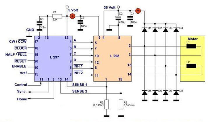 Stepper Motor Driver Circuit with L297/L298 The circuit is mainly composed of two stepper motor dedicated drive integrated circuits L297 and L298. The main function of L297 is pulse distribution. It generates output logic pulses at its output terminals A, B, C, and D to drive L298. L297 also has two PWM choppers to control the phase winding current and realize constant current chopper control to obtain Good torque frequency characteristics. The X-axis pulse from HDR1 (pin 2) enters the CLOCK (pin 18) of U1 (L297) and is processed by U1 at its output terminals A, B, C, D, C (pins 4, 6, 7, 9) to generate The output logic pulse enters U2 (L298) to drive the double H bridge at its output terminals (pins 2, 3, 13, and 14) to output step pulses to drive the stepper motor to rotate. L298 is a dual H-bridge high voltage and high current power integrated circuit driver. L297 and L298 are used to form a complete drive system, which can drive two-phase stepper motors with a maximum voltage of 46V and a current of 2A per phase. The SYNC (pin 1) of U1 is the synchronization pin connected to the pin 1 of U3 and U5 to realize the synchronization of multiple L297s.
 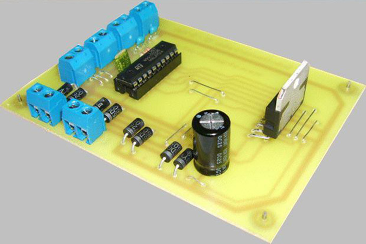 Stepper Motor Driver Control Board The ENABLE (pin 10) of U1 enables the control pin to control the output logic. When it is low, INH1, INH2, A, B, C, D are all forced to low level to make the L298 driver not work. CONTROL (pin 11) is used to select the control of the chopper signal. When it is low level, the chopper signal acts on INH1, INH2, and when it is high level, the chopper signal acts on the A, B, C, D signals. The former is suitable for the single-stage working mode and the two modes can be used for the stepping motor of the bipolar working mode. The VREF (pin 15) of S1U1 is the reference voltage adjustment pin, and the voltage of this pin is adjusted to set the peak current of the phase winding of the stepper motor.
 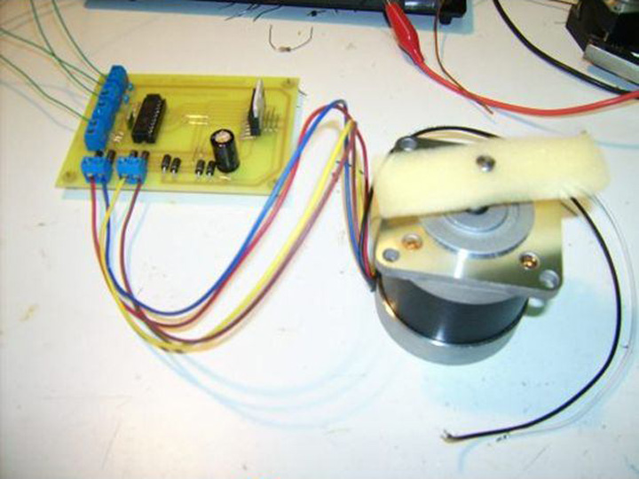 Stepper Motor Driver Kits The cw/ccw (pin 17) of U1 is the pin for specifying the rotation direction of the X-axis stepper motor, and the direction specifying signal for the X-axis from HDR1 (pin 6) is connected to this pin. HALF/FULL (pin 19) is the excitation mode control pin. When it is high, it is a half-step driving mode, and when it is low, it is a full-step driving mode. RESET (pin 20) is an asynchronous reset signal, and its function is to reset the pulse distributor. D3-D26 are the freewheeling diodes of the H-bridge of the L298 driver.
How to Setup Mach3 CNC Controller?
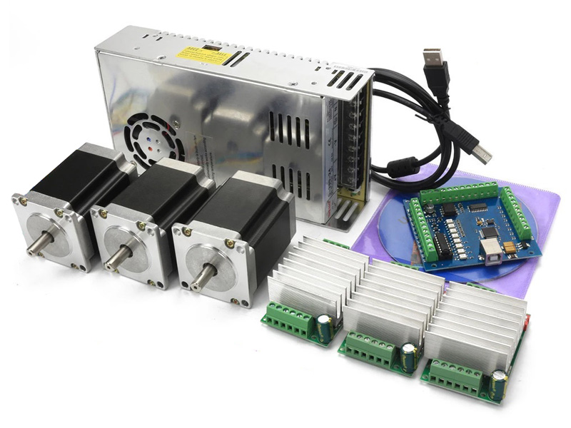
Mach3 is the most commonly used CNC controller for CNC machines. Its installation is simple. First, insert the Mach3 motion card on the computer motherboard. In the Windows operating system, the Mach3 driver will be installed by default. USB Mach3 3 Axis CNC Controller Kit You can also choose DSP, NcStudio, Mach4, Syntec, OSAI, Siemens, LNC, FANUC, and other CNC controllers.
How to Install & Use CAD/CAM Software?

The most common CAD/CAM software for CNC machines include Type3, ArtCAM, Cabinet Vision, CorelDraw, UG, MeshCAM, Solidworks, AlphaCAM, MasterCAM, UcanCAM, CASmate, PowerMILL, Aspire, Alibre, AutoCAD, Fusion360, Autodesk Inventor, Rhinoceros 3D, which can design 2D/3D drawings to generate machining tool paths.
CAD/CAM Software
How to Assemble CNC Machine Kits?
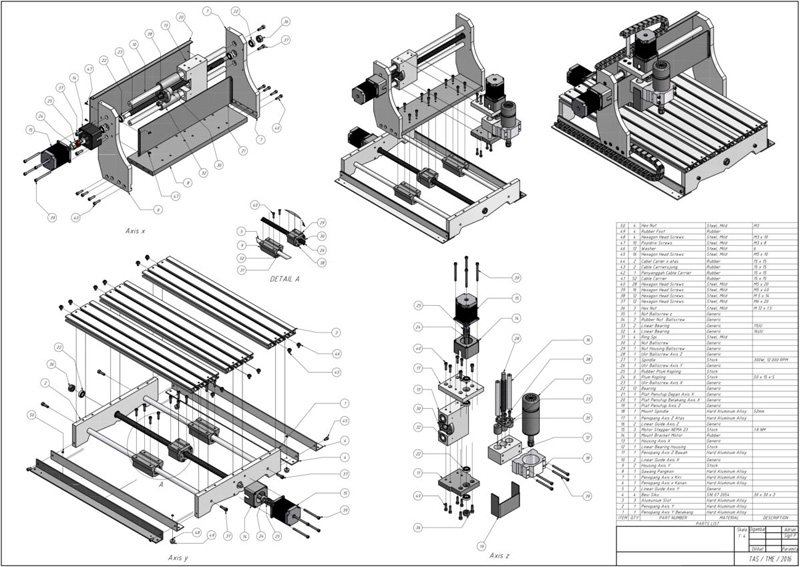
The bottom table, X-axis carriage, Y-axis worktable, and Z-axis carriage are made by a bending machine with 1.5-2mm cold-rolled steel plates, which can ensure the most ideal machining accuracy. If there is no benders, it can also be manually bent with a hand hammer on a large vise. During hand hammer processing, a pad iron should be added to the work piece to avoid leaving hammer marks on the work piece. After bending, further shaping is required. None of the planes are warped and form a 90-degree angle to each other. In order to ensure the correct punching position, the needle point of the scribing needle that is parallel and perpendicular to the first scribing line should be thin, the scribing line should be accurate, and the sample punch positioning socket should be careful and accurate. CNC Machine Kits For example, punch a hole with a diameter of 6 mm in two times. First, use a 4 mm diameter drill to drill the hole. Determine whether the 4 mm diameter hole is accurate according to the cross positioning line. If it is not accurate, use a garden assorted file to correct it. , and finally ream the hole with a 6mm drill bit, so that the hole position error is relatively small. The gantry can be cut with a hand saw from the iron keel of the anti-static floor with a wall thickness of 1.2mm according to the drawing, and it can be bent, processed and shaped on a vise. The light bar used as the X, Y, Z three-axis guide rail requires a smooth surface with a smooth diameter of 8-10mm. It can be solved by dismantling the slide rail of the used dot matrix printer and the inking rubber roller in the old laser printer cartridge. The two smooth bars in each direction should be of equal length and the end faces should be flat. Drill holes in the center of the end faces to tap M5 wire, and fix them with 5mm bolts. The workmanship must be horizontal and vertical, especially the two light bars in each direction must be absolutely The parallelism is very important, it determines the success or failure of the production. The lead screw of the three axes is a lead screw with a diameter of 6mm and a pitch of 1mm. This lead screw can be used to cut the required length from the long lead screw sold in the hardware store for the decoration of the ceiling. The resistance and clearance should be small, and the nut is welded in the corresponding hole of the carriage to minimize the backlash and improve the accuracy of the engraving machine. The sliding sleeve is a brass hose connector purchased in a hardware store. It is necessary to select the inner diameter slightly smaller than the diameter of the sliding bar, and then use a manual reamer to twist the inner diameter to precisely match the sliding bar. If necessary, polish the optical axis with metallographic sandpaper, cut the sliding sleeve into 6 mm long sections, a total of 12 sections, and then use a high-power soldering iron to solder it into the corresponding hole of the carriage. Do not place the sliding sleeve during welding. If the solder penetrates inside, use zinc chloride as a flux to ensure the soldering quality. When assembling, be careful that the resistance of the sliding table is small and consistent. If the resistance is large, the sliding sleeve can be reheated with a soldering iron to meet the requirements. The shaft of the stepper motor and the screw rod are connected through a copper tube of a 6mm diameter rod antenna. The screw rod and the copper tube are firmly welded and ensured to be concentric. The other end of the copper tube is inserted into the stepper motor shaft, and then drilled horizontally. A pin is inserted into a small hole to fix it, and the other end of the screw rod is welded with a nut on the carriage.
This CNC machine can be flexibly controlled according to the size and size of its own materials, but the whole machine should not be too large to avoid poor rigidity.
How to Operate a CNC Machine?
Before CNC machining, a list of machining programs should be prepared in advance: 1. Determine the processing procedure of the part and the tools and cutting speed used for processing. 2. Determine the contour connection point of the part. 3. Set the position of starting and closing the knife and the position of the coordinate origin. Write the numerical control instruction set according to the prescribed statement format, input the instruction set into the numerical control device for processing (decoding, operation, etc.), amplify the signal through the driving circuit, drive the servo motor to output the angular displacement and angular velocity, and then convert the components through the execution component. The linear displacement of the worktable is realized to realize the feeding. Let’s start operating a CNC machine with the 9 steps as following. Step 1. CNC Programming. Before machining, the CNC programming should be analyzed and compiled first. If the program is long or complicated. Don't program on the CNC machine, but use the programming machine or computer programming, and then back up to the CNC system of the CNC machine through a floppy disk or communication interface. This can avoid occupying machine time and increase the auxiliary time of machining. Step 2. Turn on Machine. Generally, the main power is turned on first, so that the CNC machine has the power-on conditions. Start a CNC system with a key button and the machine tool is powered on at the same time, and the CRT of the CNC control system displays information. Connection status of clam and other auxiliary equipment.
Step 3. Set Solid Reference Point. Before machining, establish the movement datum of each coordinate of the machine. This step should be performed first for the machine of the increase control system.
Step 4. Start CNC Programming. According to the program medium (tape, disk), it can be input by tape machine, programming machine or serial communication. If it is a simple program, it can be input directly on the CNC control panel by keyboard, or input segment by segment in MDI mode for remote segment processing. Before machining, the origin of the piece, tool parameters, offset, and various compensation values must also be input in the program.
Step 5. Program Editing. If the entered program needs to be modified, the working mode selection switch should be placed in the editing position. Use the edit key to add, delete, and change. Step 6. Program Inspection & Debugging. First, lock the machine tool and only run the system. This step is to check the program. If there is any error, it needs to be edited again.
Step 7. Workpiece Fixing & Alignment. Fix and align the workpiece to be processed, and establish a benchmark. The method adopts manual incremental movement, continuous movement or manual wheel movement of the machine tool. Set the starting point to the beginning of the program, and set the reference of the tool. Step 8. Start CNC Machining. Continuous machining generally uses program additions in memory. The feed rate in CNC machining can be adjusted by the feed rate switch. During machining, the feed hold button can be pressed to pause the feed movement to observe the processing situation or perform manual measurement. Press the cycle start button again to resume machining. To ensure that the bowl is correct, it should be re-checked before adding. During milling, for flat curved pieces, a pencil can be used instead of a tool to draw the outline of the part on the paper, which is more intuitive. If the system has a tool path, the simulation function can be used to check the correctness of the program.
Step 9. Turn off Machine. After adding, before turning off the power, pay attention to check the status of the CNC machine and the position of each part of the machine. Turn off the machine power first, then turn off the system power, and finally turn off the main power.
FAQs
How many types of CNC machines can be build by yourself?
The most common types of CNC machines to be made by yourself include CNC routers, CNC lathes, CNC mills, CNC grinders, CNC drills, CNC lasers, and CNC plasma cutters.
How much does it cost to build CNC machine kits?
The cost of DIY CNC machine kits includes computer, control board, machine parts and accessories. Most of the cost is concentrated in hardware, which depends on the accuracy you required for you CNC machining plan, and the average cost is under $1,000.

 Stepper Motor Driver Circuit with L297/L298 The circuit is mainly composed of two stepper motor dedicated drive integrated circuits L297 and L298. The main function of L297 is pulse distribution. It generates output logic pulses at its output terminals A, B, C, and D to drive L298. L297 also has two PWM choppers to control the phase winding current and realize constant current chopper control to obtain Good torque frequency characteristics. The X-axis pulse from HDR1 (pin 2) enters the CLOCK (pin 18) of U1 (L297) and is processed by U1 at its output terminals A, B, C, D, C (pins 4, 6, 7, 9) to generate The output logic pulse enters U2 (L298) to drive the double H bridge at its output terminals (pins 2, 3, 13, and 14) to output step pulses to drive the stepper motor to rotate. L298 is a dual H-bridge high voltage and high current power integrated circuit driver. L297 and L298 are used to form a complete drive system, which can drive two-phase stepper motors with a maximum voltage of 46V and a current of 2A per phase. The SYNC (pin 1) of U1 is the synchronization pin connected to the pin 1 of U3 and U5 to realize the synchronization of multiple L297s.
  Stepper Motor Driver Control Board The ENABLE (pin 10) of U1 enables the control pin to control the output logic. When it is low, INH1, INH2, A, B, C, D are all forced to low level to make the L298 driver not work. CONTROL (pin 11) is used to select the control of the chopper signal. When it is low level, the chopper signal acts on INH1, INH2, and when it is high level, the chopper signal acts on the A, B, C, D signals. The former is suitable for the single-stage working mode and the two modes can be used for the stepping motor of the bipolar working mode. The VREF (pin 15) of S1U1 is the reference voltage adjustment pin, and the voltage of this pin is adjusted to set the peak current of the phase winding of the stepper motor.
  Stepper Motor Driver Kits The cw/ccw (pin 17) of U1 is the pin for specifying the rotation direction of the X-axis stepper motor, and the direction specifying signal for the X-axis from HDR1 (pin 6) is connected to this pin. HALF/FULL (pin 19) is the excitation mode control pin. When it is high, it is a half-step driving mode, and when it is low, it is a full-step driving mode. RESET (pin 20) is an asynchronous reset signal, and its function is to reset the pulse distributor. D3-D26 are the freewheeling diodes of the H-bridge of the L298 driver.

